
Automotive OEMs today face unprecedented system complexity. Electronic Control Units (ECUs) are no longer isolated controllers: they are interconnected compute nodes orchestrating power trains, perception stacks, thermal management, charging systems, and motion control.
Yet DFMEAs and PFMEAs are still mostly created manually, relying heavily on engineering memory, tribal knowledge, and inconsistent spreadsheets passed between hardware, systems, and quality teams.
The result?
- Duplicated effort across teams
- Missing or inconsistent failure modes
- Difficulty performing multi-level propagation analysis
- Time-intensive reviews during design freezes or audits
But with modern AI — specifically agent-based reasoning over system graphs and historical FMEA data — there is now a way to automate the generation of failure modes, causes, effects, and mitigation actions while ensuring traceability, consistency, and standards alignment (ISO 26262, AIAG-VDA).
This article walks through how Saphira AI enables this transformation, using automotive ECU hardware as the anchoring use case.
1. The Challenge: Manual ECU-Level FMEAs Don’t Scale
A typical ECU DFMEA involves analyzing:
- Microcontrollers & safety monitor cores
- Voltage regulators, FETs, power stages
- CAN/LIN/FlexRay/Ethernet interfaces
- Input sensors & output drivers
- Memory (Flash, SRAM, ECC)
- Power supply sequencing & watchdogs
- Clock sources, oscillators, PLLs
- External protection circuitry
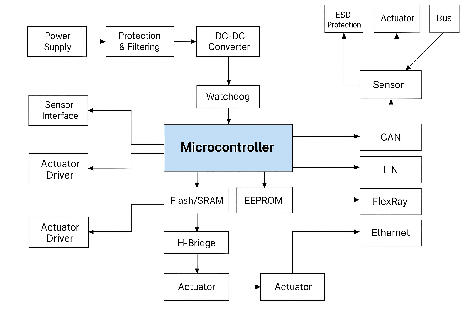
Even for a moderately complex ECU, this translates into hundreds of potential failure modes — many of which teams must analyze across system, subsystem, sub-subsystem, and hardware component levels.
AI solves two core limitations in today’s workflows:
- Reuse — engineers often fail to reuse known failure mechanisms across projects.
- Consistency — causes, effects, and mitigations drift between teams and program lines.
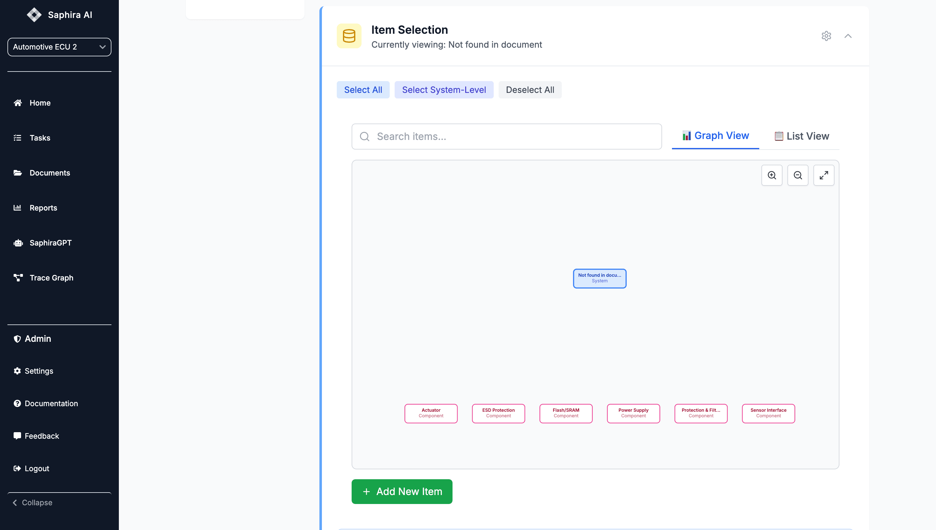
2. System Modeling: AI Understands the ECU’s Structure
Saphira begins with the ECU architecture: a block diagram, schematic, or SysML extract. The AI converts it into a graph representation where nodes = components and edges = interactions.
What the AI extracts automatically:
- Power tree (buck regulators, current sense, reverse polarity circuits)
- MCU functional partitions
- Interfaces (SPI, I²C, CAN, LIN, Ethernet)
- Safety islands and diagnostics
- Redundant paths (dual sensors, lockstep cores, watchdogs)
This becomes the foundation for the FMEA generation engine.
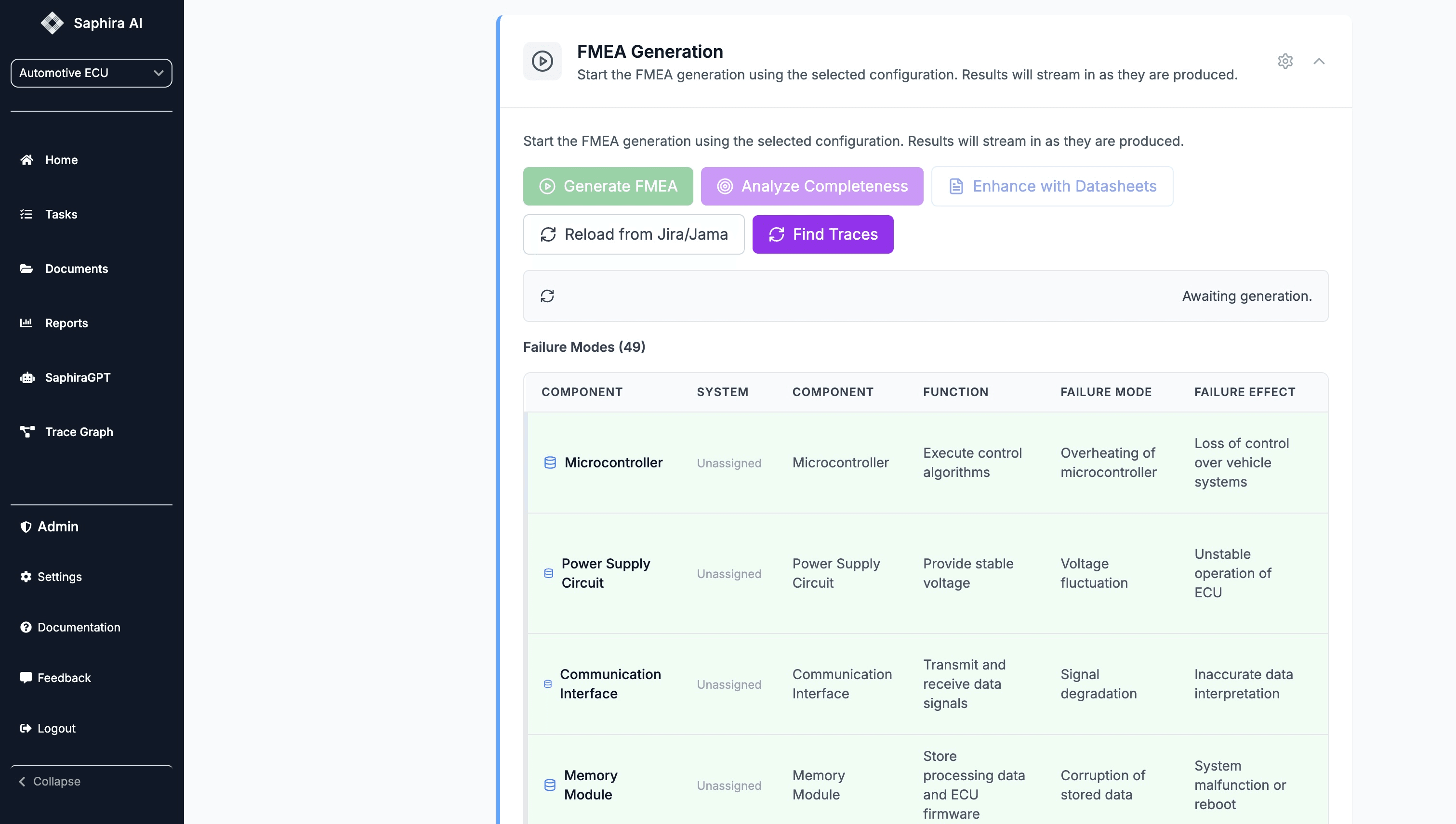
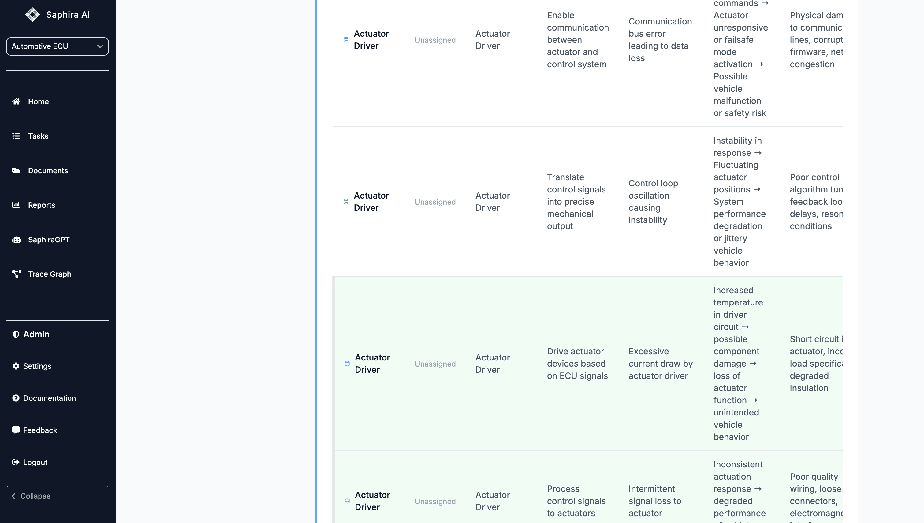
3. Automated FMEA Generation for ECU Hardware Components
Once the ECU architecture is understood, the system generates structured DFMEA/PFMEA content:
Examples of Automatically Generated Failure Modes
- MCU Core: clock drift → incorrect PWM modulation → torque instability
- Voltage Regulator: thermal runaway → undervoltage reset → limp mode activation
- CAN Transceiver: bus-off condition → loss of torque command → hazardous behavior
- Gate Driver IC: shoot-through risk → excessive current → thermal shutdown
Each failure mode includes:
- Function
- Technical failure mode
- Failure mechanism (cause)
- Local + vehicle-level effects
- Recommended actions
- Diagnostic detection paths
- Severity / occurrence / detection ratings
4. Function Reuse & New Failure Mode Inference
AI does two things simultaneously:
A. Reuse patterns from prior FMEAs
If a power-stage layout resembles a previous ECU, Saphira automatically carries over validated mitigations:
- Gate driver dead-time configuration
- Overcurrent protection thresholds
- Thermal derating strategies
B. Infer new items when interfaces or architecture differ
If a team introduces a second CAN interface or a new sensor topology, the AI detects new failure paths via graph deltas.
This hybrid reuse/inference approach improves both completeness and consistency.
5. Multi-Level Dependency Mapping Across System → Subsystem → Component
FMEAs are not isolated tables. The failure of a component propagates upward.
AI automatically computes:
- How a component’s failure affects subsystem behavior
- How subsystem failure affects vehicle-level safety goals
- Whether required safety functions exist for the failure path
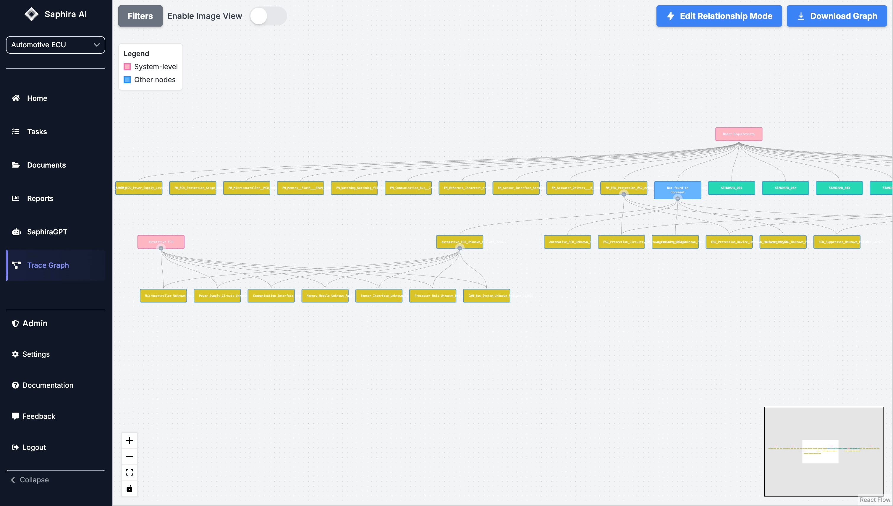
This means engineers see not only the failure mode — but its functional impact.
6. Completeness Checking & ISO 26262 / AIAG-VDA Alignment
AI performs multi-stage validation:
1. Structural Completeness
- Identifies missing causes
- Missing effects
- Missing detection/controls
- Dangling nodes
2. Standards-Based Consistency
- Checks alignment to ISO 26262 Part 5/6 hardware metrics
- AIAG-VDA 7-step compliance
- Ensures actions match severity classifications
3. Traceability Validation
- Links ECU-level faults to safety goals
- Ensures every failure is reachable in a fault tree
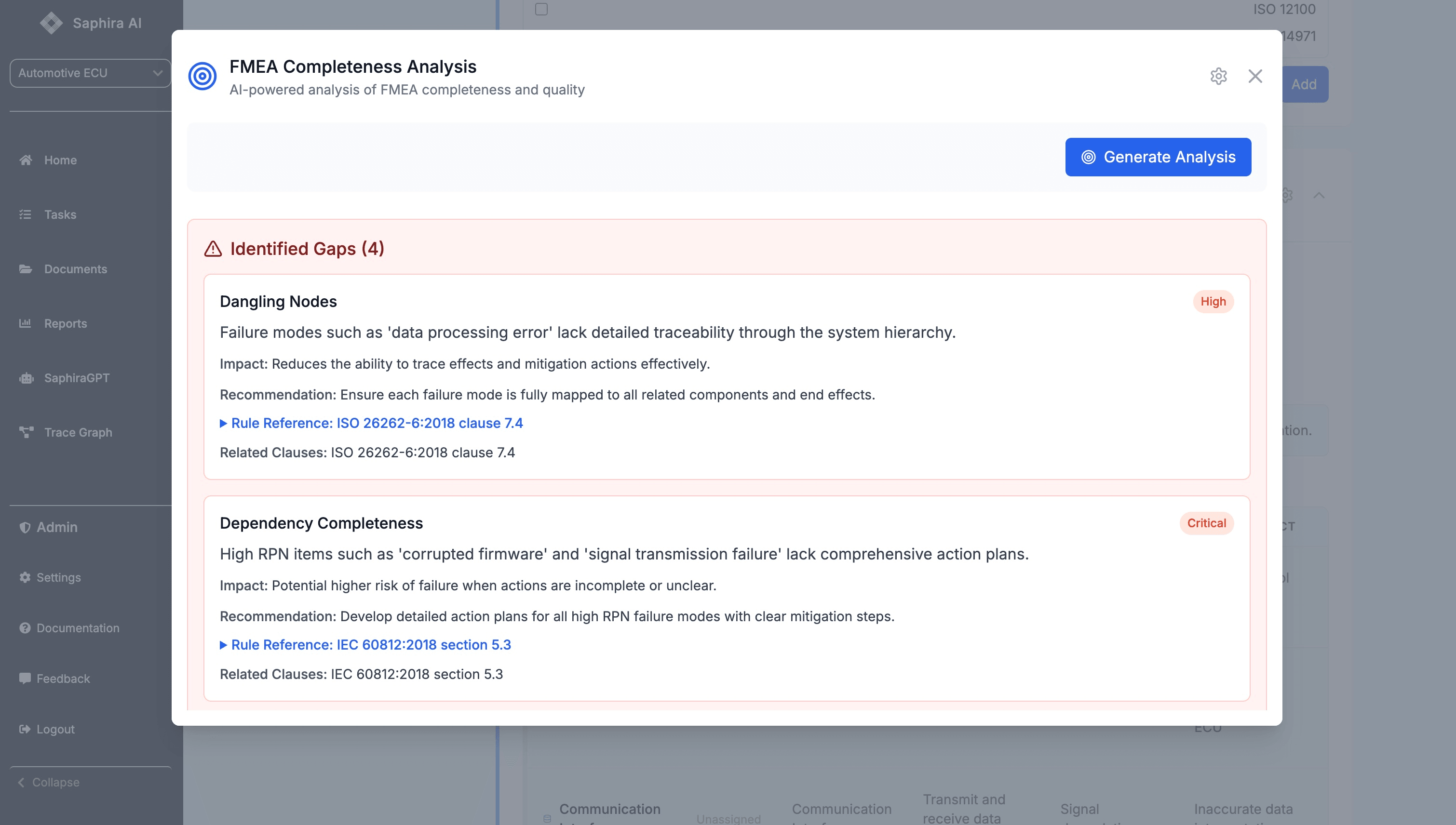
This replaces hours of moderator cross-checking.
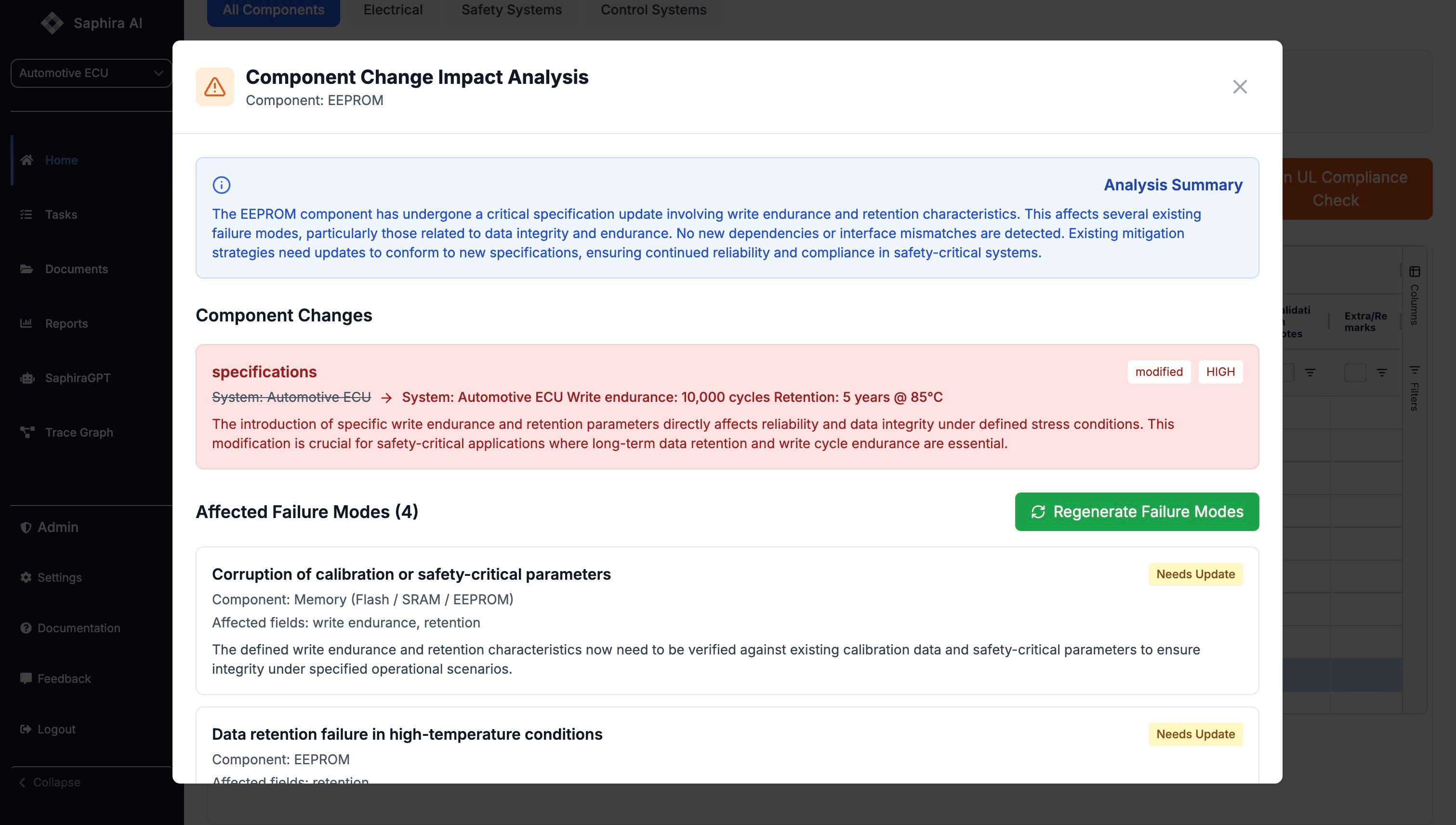
7. Change Impact Analysis for Hardware Revisions
Hardware revisions are constant: new regulator, new MCU, different PCB layout.
AI automatically:
- Detects architecture differences
- Regenerates affected failure modes
- Highlights functions no longer satisfied
- Flags mitigations requiring updates
This is enormously valuable in rapid ECU iteration cycles.
8. ECU-Level FMEAs Become Repeatable, Reusable, Auditable
The combined effect:
- Reduced engineering effort
- Far higher consistency across teams
- Traceable artifact chains for audits and assessments (TÜV, UL, DEKRA)
- Faster design cycles with fewer surprises in late-stage reviews
This is exactly what automotive and aerospace teams have been asking for: a systematic, automated, multi-level approach to FMEAs.
9. Demo Video Segments
These will be added soon!
Video 1 — Importing an ECU Architecture and Extracting the Hierarchy
https://www.youtube.com/watch?v=DPijjD3dPnY
Video 2 — Automated Failure Mode Generation
https://www.youtube.com/watch?v=nCA8D_VxjL8
Video 3 — Completeness Analysis & ISO Checks
https://www.youtube.com/watch?v=OSmkFUCk4ag
Video 4 — Traceability & Propagation View
https://www.youtube.com/watch?v=OKPRFDwQPXI
Video 5 — Updating FMEA After ECU Revision
https://www.youtube.com/watch?v=9ujzjOG4MwI
Conclusion: AI Transforms the Way Automotive FMEAs Are Built
For decades, DFMEAs and PFMEAs for ECUs have required:
- Deep tribal knowledge
- Manual translation across engineering domains
- Painstaking consistency checks
- Repeated work across platforms
With Saphira AI’s multi-level modeling, inference, completeness validation, and traceability reasoning, automotive FMEAs become:
- Faster
- More consistent
- More comprehensive
- More audit-ready
And ultimately, they help OEMs deliver safer, more reliable vehicles with less engineering overhead.